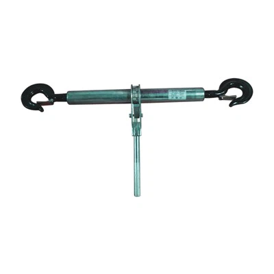
Transmission line yoke plates are the core connecting components of transmission line hardware. Their core function is to realize the force flow transmission and multi-directional connection of conductors, insulator strings, tower hanging points, or other hardware. Their structural design must meet three core requirements: strength matching, stress balance, and convenient installation. The structural composition revolves around the design of "load-bearing body + connection interface + auxiliary reinforcement/adjustment components".
Regardless of the type of connector plate, the core structure includes the following key components to ensure connection stability and mechanical reliability:
Mainboard: Bearing and transmitting the tensile, compressive, and shear forces of the transmission line, it is the core of the transmission line yoke plates. It is usually made of Q235/Q345 low-alloy high-strength steel, stainless steel, or forged aluminum (for light load scenarios), and is formed by forging, stamping, or machining. The shape is mainly rectangular, circular, or triangular. The thickness is designed according to the line voltage level (110kV/220kV/500kV/UHV) and load requirements (the higher the voltage and the larger the conductor cross-section, the thicker the mainboard). Sharp edges are avoided. The surface is treated with hot-dip galvanizing or anti-corrosion coating to prevent corrosion from outdoor environment (wind, rain, salt spray, ice and snow) and extend service life.
Connection interface: Enables precise docking with components such as insulator strings, conductors, mounting plates, and guy wires to ensure smooth force transmission. Multiple precision-positioned bolt holes are reserved for fastening with other hardware using high-strength bolts (such as hot-dip galvanized high-strength bolts). The hole spacing and diameter must match the matching hardware to avoid force deviation.

What are the design principles when designing transmission line yoke plates?
Balanced stress: The central axis of all connection interfaces must be aligned with the force direction of the main board to avoid eccentric stress leading to localized stress concentration and reduce the risk of fracture; Balance between lightweight and high strength: While meeting load requirements, the self-weight of the connecting plates is reduced by optimizing the shape of the main board and selecting high-strength alloy materials, thereby reducing the load-bearing pressure on the tower; Compatibility: Structural dimensions (bolt hole spacing, interface type) must comply with national standards such as GB/T 2314-2018 "General Technical Conditions for Power Fittings" to ensure interchangeability with insulators, clamps, and other fittings from different manufacturers; Convenient operation and maintenance: Sufficient installation and operation space is reserved, and bolt holes, adjustment mechanisms, and other parts are easily accessible for tools, reducing the difficulty of high-altitude operations.
What are the structural differences between different types of Transmission Line Yoke Plates?
Tension Yoke Plate: Mostly rectangular or isosceles triangles similar to L-shaped connectors. As the core component bearing conductor tension, the main board is thick and often made of high-strength alloy steel, offering excellent tensile and shear resistance.
Suspension Yoke Plate: Includes various subtypes with significant structural differences. The main board is thinner and lighter, only needing to bear the vertical weight of the conductor. Some models have pre-drilled holes for installing counterweights and shielding rings to address line vibration and uneven electric field issues.
Adjustable Yoke Plate: Its structure differs greatly from traditional fixed connectors. Most are modular structures, and some adjustable connectors also feature grooves, sliders, or multiple sets of bolt holes for fine-tuning the connection angle and spacing.