
Today, we'll be discussing the installation dimensions of Rectangular Yoke Plates. These dimensions aren't arbitrary; they are determined by six key factors: tower structure, insulator string type, conductor type and split spacing, mechanical load, on-site installation space, and electrical safety distances. Deviations in these dimensions can lead to anything from assembly failures to serious safety hazards like uneven stress, vibration fatigue, and flashover.
The installation dimensions of Rectangular Yoke Plates must be based on technical specifications, which is the prerequisite for dimension calculations. Our company typically uses the tower drawings provided by the user, including the tower general plan, insulator hanging point layout diagram, and crossarm structure diagram, as the primary basis for determining the hole spacing, center distance, and installation space. Secondly, the insulator string parameters are crucial: the center spacing of double-strand insulators, the dimensions of connecting hardware, the conductor type, the center spacing of double-split conductors, the connection dimensions of tension clamps and suspension clamps, and the rated mechanical load, which determines the plate thickness, material, hole diameter, and bolt specifications.
A complete set of manufacturable and installable Rectangular Yoke Plates must specify the following 12 installation dimensions, none of which can be omitted: center distance between insulator connection holes, center distance between conductor clamp connection holes, total length of the connecting plate, total width of the connecting plate, plate thickness, diameter of connection holes, hole arrangement, size and location of corona ring reserved holes, edge chamfer radius, galvanized layer thickness, bolt specifications and tightening torque, minimum electrical clearance and creepage distance. We will now introduce these in detail.
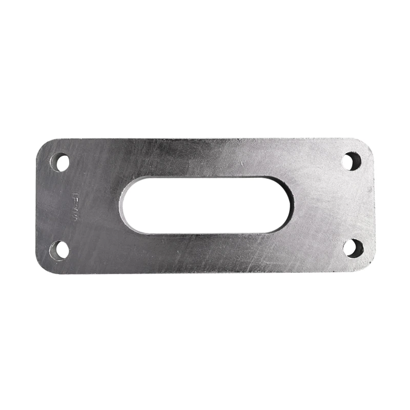
The center distance L between insulator connection holes is the most critical installation dimension for rectangular Yoke plates. It is usually marked on the tower crossarm hanging point diagram or determined by the insulator string structure to determine the design center distance of double vertical strings. Common values are 400 mm, 450 mm, 500 mm, and 600 mm. For renovation projects, on-site measurement can be performed by directly measuring the center distance between the hanging points of the two insulator strings. Our accuracy requirement is ±1 mm. Excessive hole distance deviation will cause the insulator string to tilt and affect the stress area.
The center distance W between the connecting holes of the conductor clamp is a key parameter determining the conductor matching degree. It is used for the center distance of the holes in tension clamps and suspension clamps for connecting double-split conductors. The common design spacing of double-split conductors is 400 mm, 450 mm, and 500 mm. This size is determined by the line voltage level and conductor type. 400 and 450 mm are commonly used for 220 kV lines, and 450 and 500 mm are commonly used for 330 kV ~ 500 kV lines. The hole distance W of the clamp must be completely consistent with the hole distance of the clamp body, otherwise assembly is not possible.
The total length A and total width B ensure installation space and electrical safety. The total length A = insulator hole spacing L + safety margin at both ends, which is usually 50~80 mm. This ensures installation and operation space, avoids sharp-corner discharge at the ends, and meets the requirements for hardware hoisting space. The total width B = clamp hole spacing W + upper and lower safety margin, which is usually 40~60 mm. If it is a high-altitude or heavily polluted area, the size needs to be increased.
The thickness t of Rectangular Yoke Plates is determined by the mechanical load. Plate thickness is not an empirical value, but directly determined by the rated mechanical load, and is the core of strength and safety. Insufficient thickness will directly lead to tensile fracture, bending deformation, vibration fatigue cracking, and the thickness must meet the minimum destructive load required by the standard.
The connecting hole diameter D can be directly matched with bolts and fittings. If directly connecting ball heads, cup heads, or UB mounting plates, the hole diameter must strictly match the fitting pin diameter. The hole diameter tolerance H12 ensures smooth assembly and prevents excessive clearance.
When calculating the dimensions of Rectangular Yoke Plates, a complete process is required. First, all basic data is collected, then dimensional sketches are drawn, force and electrical clearance checks are performed, and the drawings are confirmed with the user before finalization, production, and shipment can begin.